


|
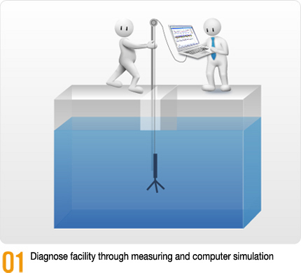
Based on years of experience on diagnosis, design, verification techniques, we developed 7-STEP DESIGN system for the most optimum Mixing Process development. |

|


![]()

|
|
|
 |
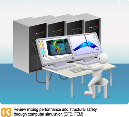
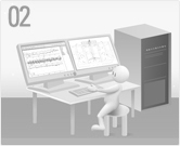
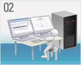
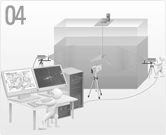
Design verification technique which would use Computer Analysis to predict and analyze flow pattern and mixing performance. To have analysis more reliable, various factors should be carefully considered and analyzed and in order to do so, lots of experience would be vital. |
|
|
|
|
|
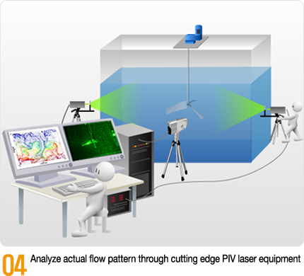
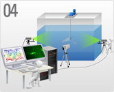
This technique would use laser beam sheet to create 2 or 3 dimensional velocity map so actual flow pattern and velocity distribution can be examined.
|
|
|
|
|
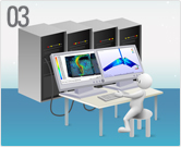
Design verification technique which would analyze and diagnose Mixer*s structural safety by using Computer simulation. Deflection load on mixers when operating would be analyzed to predict and prevent destruction and damage to the mixers due to load, vibration and etc. |
|
|
 |
|
|
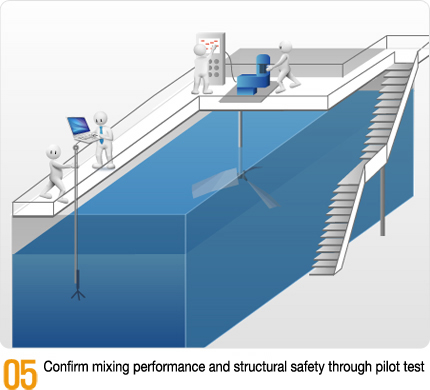
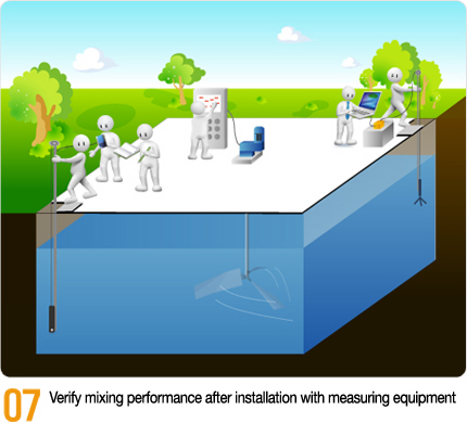
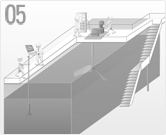
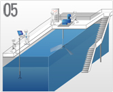
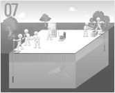
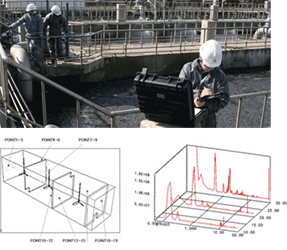
Verifying mixing condition using various measuring equipment after the mixer has been installed. The result is subject to be analyzed and reviewed to confirm its performance. |
||
![]()
 |
||
 |
Fixed Operation (On/Off) |
- Used from 70 to 80s for vertical and horizontal paddle flocculator - Change rpm by using belt pulley and etc - Low energy Efficiency |
|
Variable Operation (Inverter) |
- Used from 80 to 90s for vertical turbine type mixer - Simply change of rpm by using inverter - Concept of Gradient Velocity has not yet applied |
|
|
G Value Operation |
- Introduction of G Value (Gradient Velocity) has been made after 90s - Control precise impeller*s rpm by using exclusive program which calculates and PD control - Remote Monitoring Control at central control center and integrated operation are possible |
|
|
GOPT Optimum Operation |
- Addition to G Value Operation, additional control factors like turbidity (chemical dosage), retention time and others were added. - Suitable for processes where seasonal or daily factors must be considered for operation - Recommended for water treatment plant*s rapid mixing and coagulation mixing process |
|
 |
||
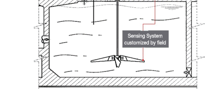 |
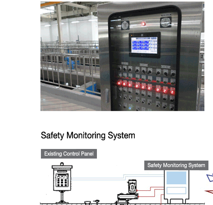
This is remote monitoring system for parts underwater and driving part. This system can prevent equipment*s destruction from unusual operation. This is suitable for unmanned facility or plant where big mixer has installed. |
|
![]()
 |
Impeller is critical part for mixing performance, and it is very technologically enhanced. It took us years of research, test and experience to develop technology so we can design impeller as each process needs. |
||
 |
 |
||
|
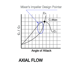
- Custom design to generate proper flow pattern for each mixing process - Design angle of attack for higher flow force with low power |
|||
 |
|||
 |
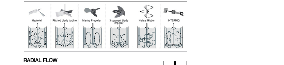
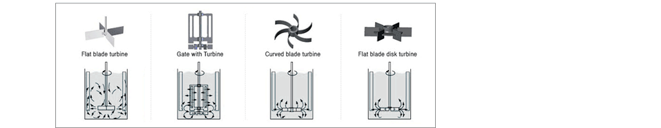
1. Directed to axial flow so it is parallel to the shaft 2. It is flow to make shear rate steady 3. Spread mixing flow to entire tank according to process* requirement 4. Examples of application are flocculation, solid suspension, mixing and etc |
 |
|
 |
|||
 |
1. Directed to radial flow so it is orthogonal to the shaft 2. Within impeller zone, it is flow which creates local shear rate 3. Spread mixing flow to parts of tank according to process* requirement 4. Examples of application are chemical mixing, low liquid level, solid suspension and etc |
 |
|
 |
|||
|
|
|
|
|
![]()
 |
 |
|
|
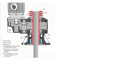
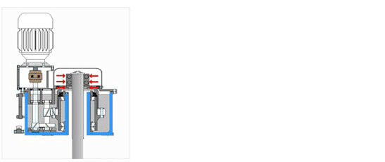
Drywell Type Impeller shaft and oil bath have been completely blocked by output shaft so that oil leakage can be prevented. Hollow Shaft Assembly Method Shaft is inserted within hollow shaft so that its axial load from shaft deflection is spread to entire hollow shaft. Therefore gear and bearing have 100,000 hours of lifetime. Shrink Disk to Fix Shaft Using shrink disk, the shaft which is inserted within hollow shaft is fixed. It is much more stable and easy for maintenance. |
 |
|
|
|
||
|
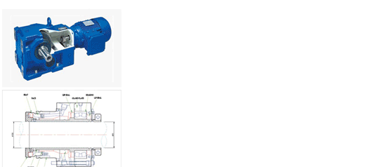
Bottom Assembled Drywell Type All-in-one oil bath type at the bottom is applied so that gearbox*s output shaft and impeller shaft are completely blocked to prevent oil leakage. Hollow Shaft Assembled at the top The shaft is inserted within gearbox*s hollow shaft, and using clamp, the shaft and hollow shaft are assembled together. It is much convenient for maintenance. RS B 0062 Acquired in Reliability Evaluation (Korea Institute of Machinery & Materials) |
 |
|
|
|
||
|
Gear Driven Mechanism (High Performance 3 Stage Helical Bevel) Highly efficient driving and optimum design for each flow condition due to gear driven mechanism. Mechanical Seal System This system is bearing type so, within certain range, shaft deflection for axial or radial direction is accommodated. CARTRIDGE TYPE It is easy to disassemble and assemble, and also very convenient for maintenance. |
|
|
|
|
||
![]()
 |
|
|
It is not after care system where remedy is applied after trouble has happened. We take measure with regular examination and maintenance activity as for preventive action. |
|
 |
